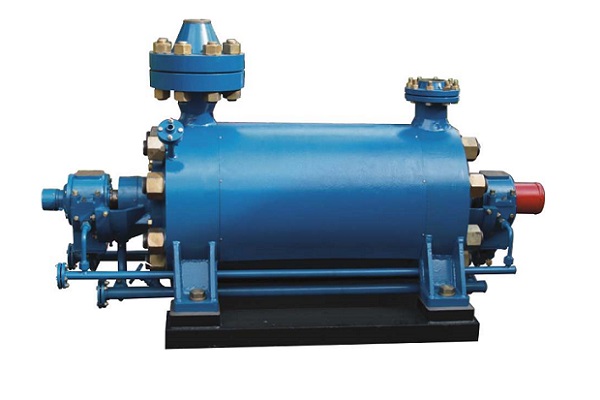
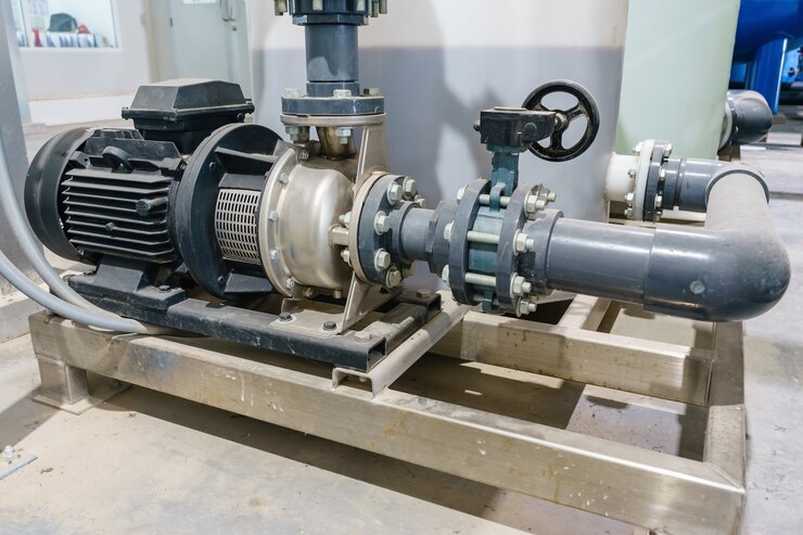
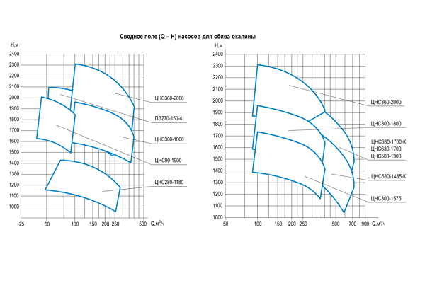
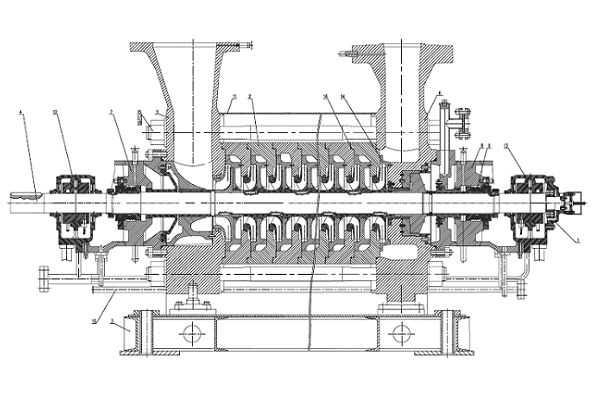
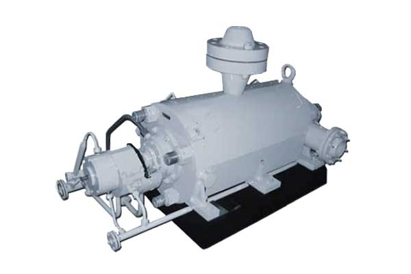
The pump casing consists of a suction casing; a discharge casing and a set of stage casings, which are concentrically aligned with respect to each other, being fitted on circular rabbeted fits, and tied up with studs (tie bolts). The tightness of joints between the stage casings, suction and delivery casings is ensured by a metal-to-metal contact of the mated surfaces, with round section joint rings (O-rings) of rubber placed in between them for additional sealing.
Renewable casing wear rings and inter stage bushes are fitted respectively in the suction casing and stage casings and in the diffusers in order to reduce internal leakage from the high (discharge) pressure area to the suction pressure side. They together with the sealing surfaces of the impellers form throttling gaps (impeller sealing or running clearances).
The suction and discharge nozzles are oriented vertically to the top.
The pump rotor is composed of shaft, impellers, balance disc, sleeves, oil throwers and fasteners.
Axial forces arising during the pump operation act on the impeller shrouds and shaft end face. They are directed towards the pump suction.
Balancing device incorporating a balance disc with balance disc seat and recirculation of balance liquid stream to the suction serves to absorb the axial thrust of the pump rotor. The extent of compensation of the rotor axial thrust varies automatically as the operating conditions of the pump change.
A thrust antifriction bearing and an automatic shaft position indicator are provided in the non-drive end bearing for the limitation of axial shifts of the rotor.
Balance disc and balance disc seat are assembled units, each of them consist of basic part and executive elements – wear rings, manufactured from special wear resistance W carbide alloy. Such design ensures long service term of balancing device and allows carrying out easy repair works when necessary.
